About this challenge:
"This design was started in October 2017, inspired on a recycled can of food and then took his name from the combination of his rounded shape and the classic rolex clock".
Challenge
Keyword'Text revision 2.0'
Last edit Mar 02.2018
About this challenge:
"This design was started in October 2017, inspired on a recycled can of food and then took his name from the combination of his rounded shape and the classic rolex clock".
Mission objective:
Making a clock with led displays and a recycled can
Description:
The dificulty of this work is based on the software layer more than the design itself.
Work:
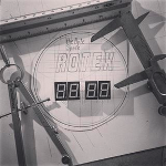
This clock was disigned to represent the hours with four digits.
The display drive:
We are using four common anode displays and thirteen input/output controller, a recycled can of food, two switches and a pcb board, some wires and leds.(Some about the original design change at the end of the project, that is a common situation when designing and those changes are not always descrived here, just the finally work.)
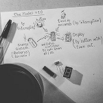
The image at left was post on the instagram account to show in more details what components were planned to be used. actually there appear a battery and a type of button that never were used, but it complete the idea of the general parts of the system.
The power source for the Rotex clock:
This plans are Standby, there is not solution for this yet, another challenges will provide this block soon later.
The final list of component used. (by the first version of the Rotex clock)
Rotex list of components.
The microcontroller diagram.
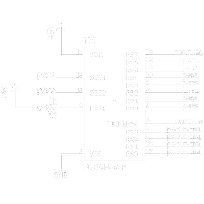
The image above show us the pinout configuratoin of the microcontroller used for the rotex clock, to drive each one of the seven segments plus one point there is one output (eight outputs RB0 to RB7).
How the microcontroller is connected to the segment display.

At left two of the four displays. The diagram shows the connections to the microcontroller as it's described in the list below.
How the toggle switches work.

At right the switches (S1,S2) are connected both to a pulldown resistor (R1), whose state ir going to be read by the 'switch-in' microcontroller input. The two transistors control what time the buttons can pull the resistor high, this way the users can't interrupt the display refresh.
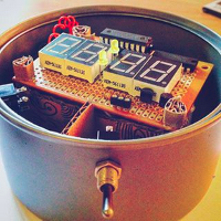
At right the full color image of the rotex clock circuit inside the can. You can see how toggle switch is working in two ways, as hour setter and supporting and holding the can lifted.
Back to homepage
Link back
Attempt
Testing the results.
...
...
I...
...
List Title
BlackByte on October 06, 2017
Back to homepage
Link back